
engineering drawing milling vice manufacturer Grasping strong production capability, advanced research strength and excellent service, Shanghai engineering drawing milling vice supplier create the value and bring values to all of customers.
 WhatsApp)
(a) Plain Vice – The plain vice is directly bolted on the milling machine table is the most common type of vice used on plain milling operations, which involves heavy cuts, such as in slab milling. Its especially low construction enables the work to remain quite close to the table.
Dual Force 5 Axis Vise Designed especially for multi-face machining of simple to complicated workpieces with a single clamping operation. These vises are small but have a large holding capacity making them ideal for 5-sided machining. Equipped with a variety of jaw options to cover a wide range of workholding applications. These unique vises deliver unrestricted all around access to the ...
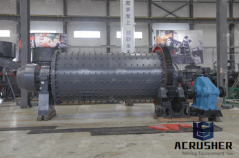
Milling Machines A milling machine is a power driven machine that cuts by means of a multitooth rotating cutter. The mill is constructed in such a manner that the fixed workpiece is fed into the rotating cutter. Varieties of cutters and holding devices allow a wide rage of cutting possibilities.
Search alphabetically for subject. More to be uploaded during the next few weeks.
The GSFC Engineering Drawing Standards Manual is the official source for the requirements and interpretations to be used in the development and presentation of engineering drawings and related documentation for the GSFC. The Mechanical Engineering .
A Small Low Profile Machine Vise: I knew my small old horizontal milling machine needed cutters, an arbor and arbor support, a drawbar, guards and a vise when I got it. It turned out it needed a lot more than that.I have a nice old Wilton 3 1/2" drill press vise, it has a fast act...
He posted a link in an Eng-Tips Forums thread to a document titled "Tips on Designing Cost Effective Machined Parts," written by Joe Osborn, from OMW Corporation. Drawings and Prints. Make things easy for the machinist. Technical drawings and other print documents are .
Dec 31, 2012· Engineering Drawing Tutorials.Orthographic Drawing with Sectional Front & Side view (Section) with question and step-wise solution. Engineering Drawing Tutorial's solution of I.O.E (T.U) and K.U ...
machines like lathes, milling machine, drilling machine etc. and also by tool makers for holding jobs. Design wise three types of vises are very common in use namely plain vise, swivel vise and tool maker's vise which is commonly known as bench vise. Vise is usually refers to a bench vise with flat, parallel jaws, attached to a workbench.

Working drawing (in.) Assembly Name: Machine Vise SPECIFIC INSTRUCTIONS: When preparing the assembly drawings, use separate balloons for each part in each viewor use only one balloon in the view that most clearly identifies the part.Prepare a complete set of working drawings with one detail drawing per sheet and the assembly drawing and bill of materials on another sheet.
Number of Pages: 8 This is a reproduction, not a photocopy, of an original Rusnok Model 850 Fixture Milling Machine Instructions and Parts Manual. This manual contains information on machine specifications, lubrication, operating instructions, spindle removal instructions, and explosive diagrams of the parts with descriptions.
Chapter 16. Projects 16-1 Introduction This chapter presents two large projects: the Milling Vise and the Tenon Jig. The projects are intended to serve either as group projects or as . - Selection from Engineering Design Graphics with Autodesk® Inventor® 2017 [Book]
machine vise digital design graphics technology jim kisiel ddgt 121 1 of 6 1/27/2011 machine vise name: course: date: dwg name: sheet no. parts list item qty part name description material 1 1 base c1 2 2 jaw plate sae #3140 3 1 handle rod c r s 4 2 handle ball sae #1020 5 2 taper pin #000 steel 6 1 vise screw sae #3140 7 1 special key sae #1020
The THORS Engineering Drawings for Machining course introduces the learner to the unique features of a machining engineering print and offers insight into the finishing processes used to manufacture the specified machined component.
The assembly drawing is of little use on its own because it needs a list to identify each individual part within the assembly. Such a parts list or item list is shown as part of the drawing in Figure 3.1. VICE ASSEMBLY DRAWING Not to scale. Figure 3.1 Assembly engineering drawing of a small hand vice
Home › engineering drawing milling vice vise - Recent models - GrabCAD - CAD Library Join 2,650,000 engineers with over 1,100,000 free CAD files Join the Community.
Engineering drawing is a suitable graphic language from which any trained person can visualize the required object. As an engineering drawing displays the exact picture of an object, it obviously conveys the same ideas to every trained eye. Irrespective of language barriers, the drawings can be

Machine Vice Models and Drawings Re. Fundamentals of Graphics Communication, Gary R. Bertoline, etal. Modeling Considerations 1. Symmetry: Sketch Dims / Constraint
Use of the vice on an angle-plate; squaring up a GM casting Fig. 11. A side-and-face cutter squaring off the ends of four bars at once. THE VERTICAL SLIDE. While a great deal of milling can be done using the vice, angleplate and vee-block alone there is no doubt that the absence of movement in the third plane – vertically- is a great hindrance.
Oct 6, 2019- "The Milling Machine for Home Machinists"This book provides the detailed knowledge you need to successfully choose, install and operate a milling machine in your home workshop. Lavishly illustrated with color photographs and diagrams, this book will help you understand which accessories are essential and which can be postponed until your activity demands them.

Toolmakers Clamps. I have a couple of toolmakers clamps which I made at school some 50 years ago, they are still working and regularly used but I thought it would be useful to have something smaller. So I scaled down the original and came up with something about two-thirds size. I have included a drawing below but sizes are very flexible.
Section 10: Basic and common symbols recognition PURPOSE This section aims to enable the student to extend their knowledge of Drawing Interpretation from Engineering Drawings produced to AS1100 standard. Objectives At the end of this section you should be able to: o Interpret information on detail drawings of engineering components.

He posted a link in an Eng-Tips Forums thread to a document titled "Tips on Designing Cost Effective Machined Parts," written by Joe Osborn, from OMW Corporation. Drawings and Prints. Make things easy for the machinist. Technical drawings and other print .
Vise-Jaw Fixtures: It is used for machining small parts. The standard vise jaws are replaced with jaws conforming to the shape of the part to be fitted. Their use in limited only by the sizes of the vises available. Type # 4. Vise-Jaw Fixtures: It is used for machining parts having evenly spaced machined surfaces. (Refer Fig. 28.24). Type # 5 ...
WhatsApp)